 |
 |
 |
 |
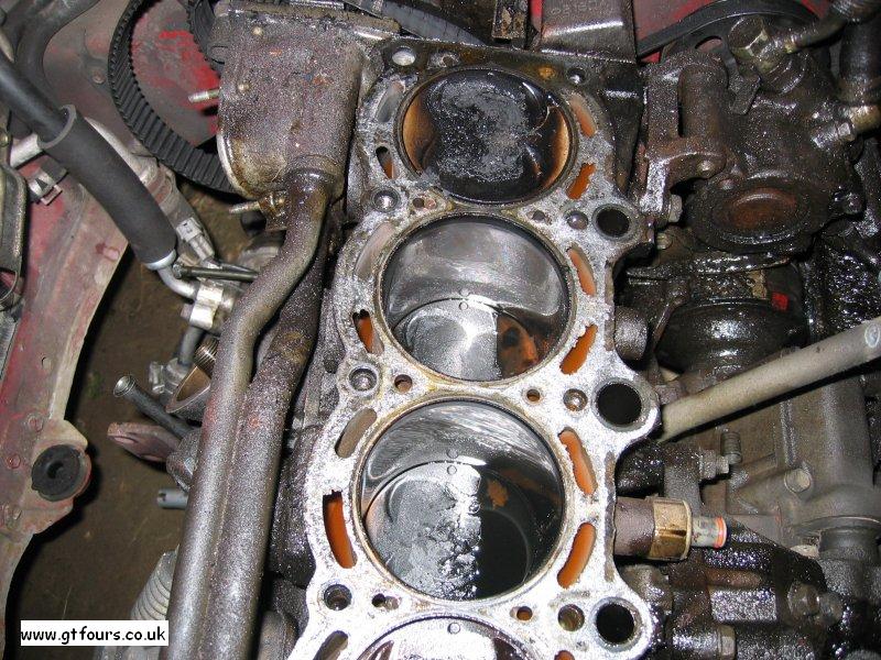
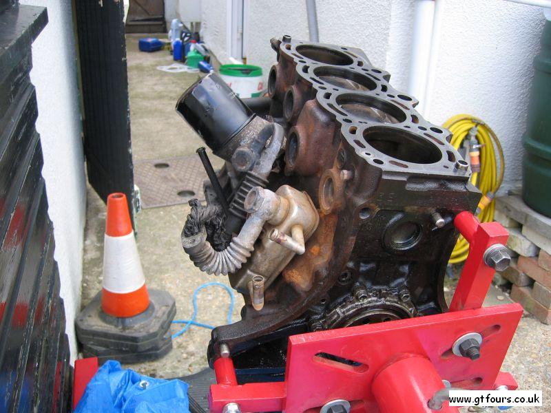
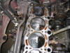
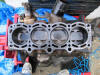
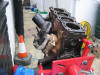
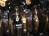
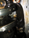
| Cylinders 1 - 3 |
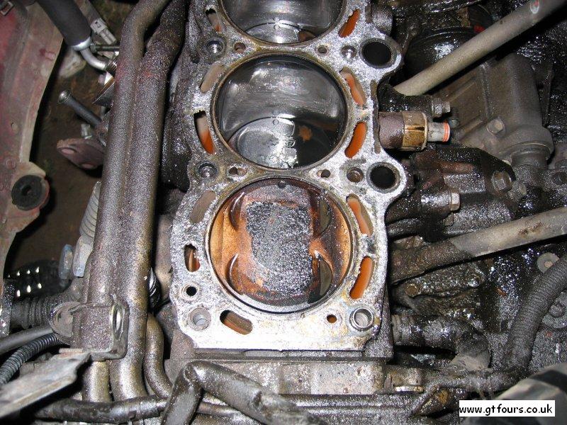
Cylinders 3 and 4. Note the knock sensor on the side of cylinder 3 |
From this view you can see the mark on each piston denoting the correct fitment |
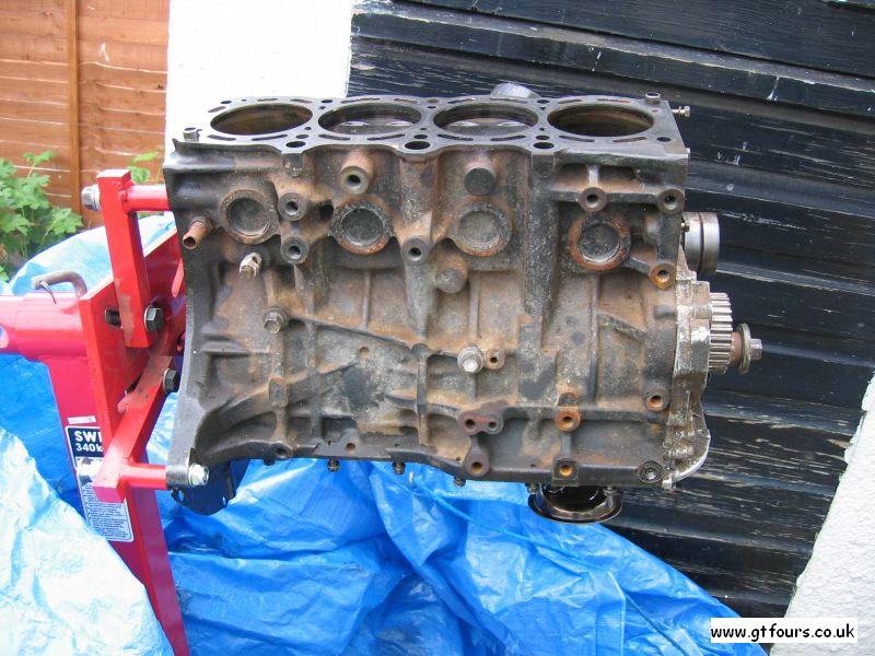
Side view with sump removed |
| |
 |
 |
 |
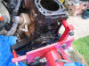 |
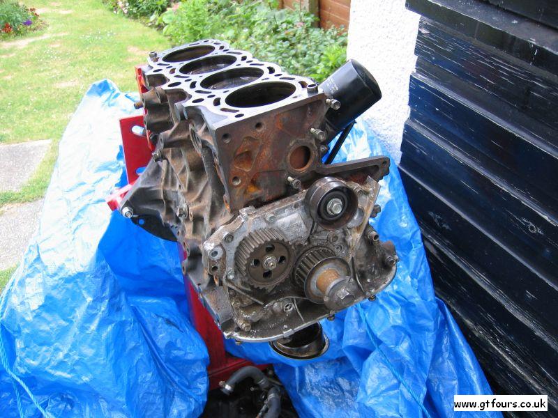
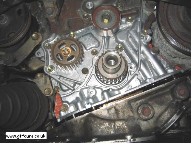
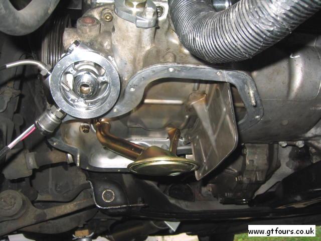
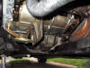
| This view clearly shows the oil pump assembly, crank pulley and idler |
The oil pump assembly, as fitted to a 205 |
Oil filter etc |
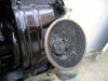
Flywheel end |
| |
 |
 |
 |
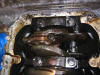 |
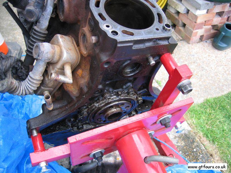
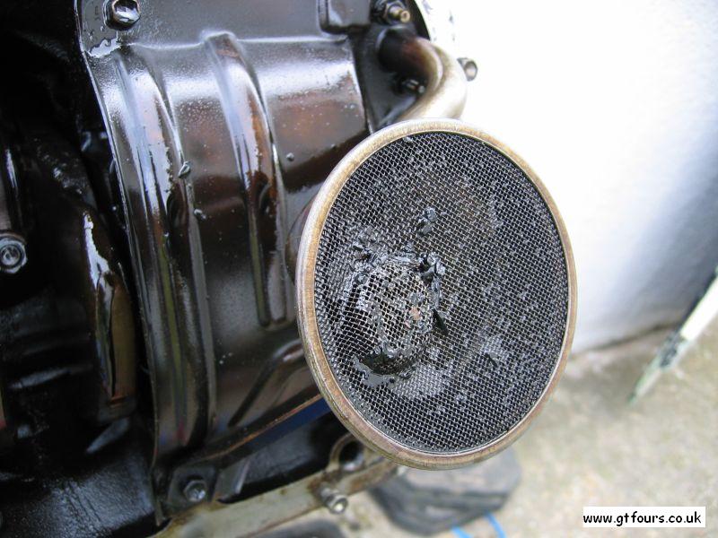
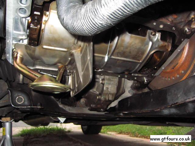
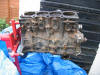
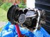
| With the sump removed the strainer and oil pump pick can be inspected |
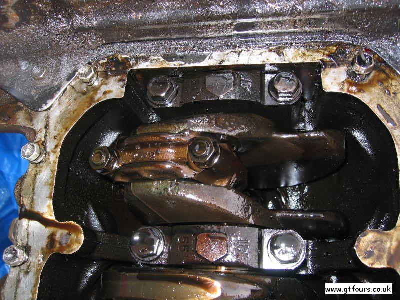
Bottom end view |
The mesh on the strainer stops larger foreign objects from entering the oil pump... |
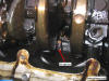
Big end and main bearings |
| |
 |
 |
 |
 |
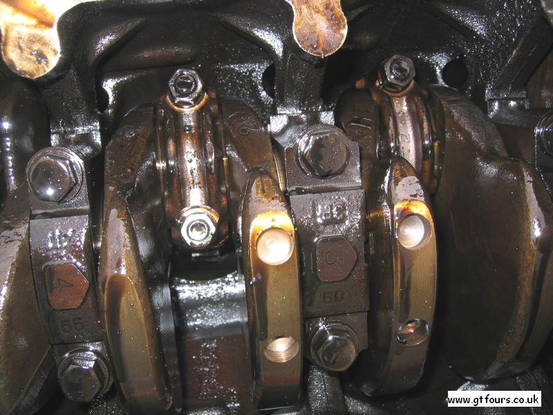
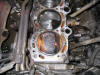
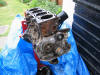
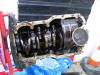
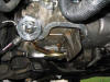
| Another view of the bearing caps |
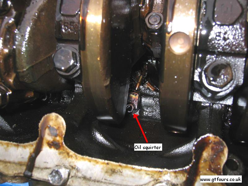
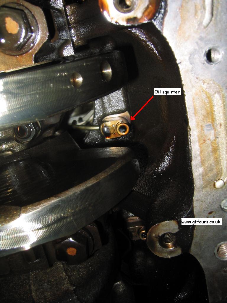
If you look closely you can see one of the oil squirters used to cool the underside of the pistons... |
The 205 also utilises oil squirters to aid in cooling the pistons |
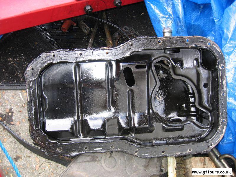
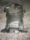
The sump. Note the baffling. The 205 sump arrangement is vastly different |
| |
 |
 |
 |
 |
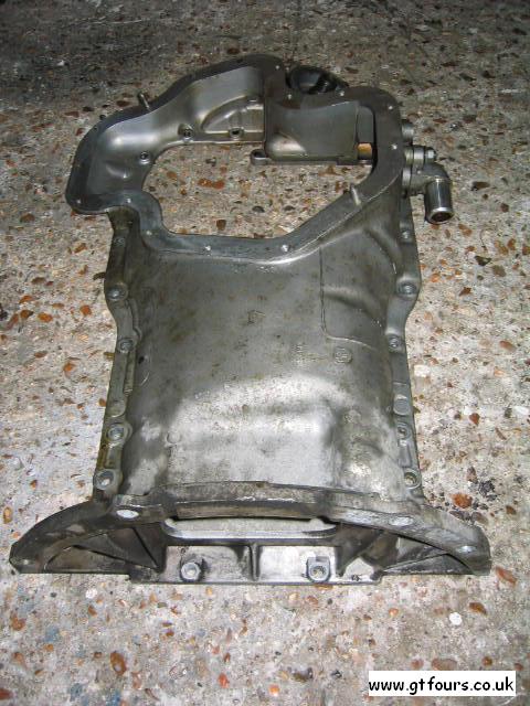
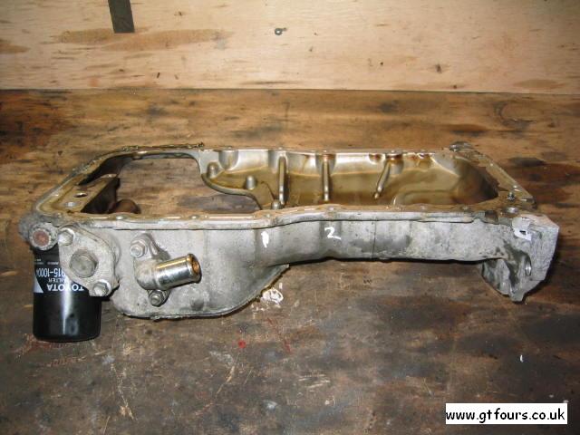
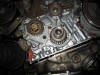
| As you can see the 205 sump is a lot different. It comes in 2 parts, this is the main part... |
...it accommodates the oil filter and pressure regulator. A design change is apparent here as the sump extends all the way over to and bolts to the gearbox casing, for increased rigidity |
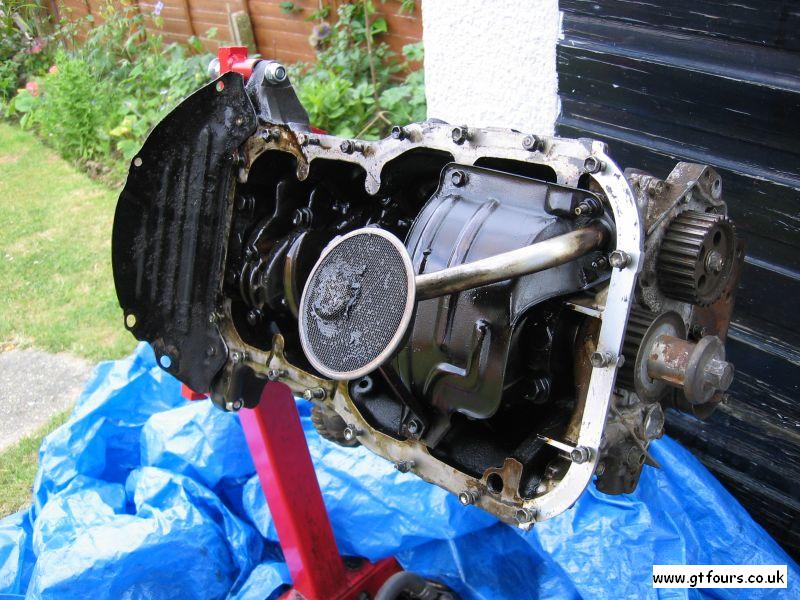
205 - under the sump is the baffling, which is bolted to the block |
With the main section of the sump in place the function of the baffling is easier to see |